
Home / Products / Water & wastewater / Oil–water separators
 Mullaly Tank Solutions – Water
Aquator® oil water separator
Class 1 dual-chamber separators that capture fuel spills and take hydrocarbons out of stormwater and wastewater, down to less than 5 mg/L at the outlet. Gravity operated, so they keep working in a power failure.
Get a price
Tell us roughly what you need. A sales engineer for your state replies within 2 business days.
Have drawings or a full spec? Use the detailed quote form, or call NSW +61 2 4964 8270 or WA +61 8 9434 1707.
Features
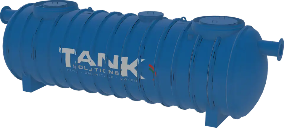
The Aquator® is a commercial oil water separator, also called an oily water separator. It holds hydrocarbons and silt in its first chamber and polishes the flow through a coalescing filter in the second, all in one FRP tank.
Class 1 outlet
Coalescing filtration reduces light liquids in the outlet to less than 5 mg/L.
Gravity operated
No pumps in the treatment path, so it works through a power failure.
Automatic oil stop valve
Closes when oil builds up, so a spill can’t discharge to the drain.
No bypass
Every litre that enters the separator is treated.
FRP construction
Virgin resin and glass fibre with integral ribs, tested during manufacture and before dispatch.
Alarmed
Silt, oil and high-water probes, with the oil alarm set at 90% of oil storage.
Where it’s used
- Service stations and refuelling areas
- Power stations, substations and switchyards
- Mining and heavy vehicle maintenance
- Wind farms
- Waste transfer depots
- Asphalt plants
What it does
- Captures and stores fuel spills
- Removes hydrocarbons from water runoff
- Discharges treated water to stormwater
- Captures silt in its own chamber
How the Aquator® works
Inlet
The inlet pipe is arranged to minimise turbulence and acts as a flame trap, stopping flammable vapours passing into the drainage system.
Retention chamber
Flow slows and separates by density. Silt drops to the silt retention chamber and oil floats to the surface, where it is held.
Coalescing filter
In the second chamber, coalescers with a polyether matrix join fine oil droplets so they separate out, taking the outlet below 5 mg/L.
Oil stop valve
A buoyant element senses the change in density as oil builds up, and closes to isolate the retention chamber.
Standard models
| Model | Nominal capacity | Max flow | Spill capture | Silt capture | Length | Diameter | Weight | Straps |
|---|---|---|---|---|---|---|---|---|
| T3.5 | 4,100L | 6L/s | 1,500L | 400L | 2,710 mm | 1,470 mm | 500 kg | 2 |
| T20 | 20,800L | 60L/s | 9,000L | 4,500L | 6,970 mm | 2,140 mm | 1,600 kg | 4 |
From the Aquator® technical data sheet (TD_TDS_007 Rev L). T20 maximum flow of 60L/s as approved by Water Corporation (AN-082). Weights, capacities and dimensions are nominal. Higher flow rates, larger spill capacities and custom tanks are available on request.
How oil water separators work, and how Class 1, coalescing plate and triple interceptor types compare, is covered in Mullaly’s oil water separator guide.
Tested by two universities
The University of South Australia and the University of Newcastle each tested the Aquator® independently against BS EN 858-1:2002 as a Class 1 separator. Their reports are available on request.
- Class 1 outlet: less than 5 mg/L of light liquids
- Tested to BS EN 858-1:2002
- Independently tested by the University of South Australia and the University of Newcastle


What’s supplied
Supplied as standard
- Single-wall FRP tank with lifting lugs
- FRP flanges to AS 4087
- Oil stop valve
- Coalescer filter
- Alarm control panel with silt, oil and high-water probes
- Manholes and risers
- Class D trafficable covers
- Hold-down straps and concrete anchors
Options
- Double-wall FRP tank
- Internal pipework
- Watertight riser covers
- Class B non-trafficable covers
Standards & testing
| BS EN 858-1 | Separator systems for light liquids. Aquator® separators are made to meet or exceed BS EN 858-1:2002, Class 1 |
|---|---|
| Independent testing | University of South Australia and University of Newcastle; reports on request (see testing) |
| AS 4087 | FRP flanges |
| Water Corporation (WA) | Separate installation manual edition; a Trade Waste Sampling Point is required on the outlet (drawing HX33-11-30) |
| ISO 9001 | Quality management certification at Tomago NSW and Kwinana Beach WA |
Downloads
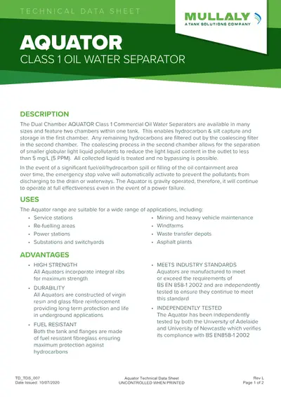
Installing an Aquator®
Install to the Aquator® operating, installation and maintenance manual. Tank Solutions can advise on application and installation for your project.
Minimum cover over the tank
| Hole | No traffic | Traffic |
|---|---|---|
| Dry hole | 300 mm backfill | 910 mm backfill, or 460 mm backfill + 150 mm reinforced concrete |
| Wet hole | 1,000 mm backfill | 760 mm backfill + 150 mm reinforced concrete |
Maximum cover is 2.1 m over the top of the tank. Traffic means highway vehicles up to H-20 or HS-20 (AASHTO). Risers must not carry slab load; leave at least 75 mm between riser and slab.
On site
- Bed on at least 300 mm of washed pea gravel (10–20 mm) or crushed stone (10–14 mm) to AS 2758
- Anchor with concrete deadmen or an anchor slab, with hold-down straps at the marked positions
- Leave 450 mm between the tank and the excavation wall in stable ground; half the tank diameter in unstable ground
- Measure tank diameter at four stages to check deflection
- Sensors and alarm fitted and commissioned by a licensed electrician
- Return the installation checklist within 30 days to validate the warranty
Maintenance
Routine
- Check the oil level after every rainstorm, or as local codes require
- Remove oil only when there is no flow
- Measure oil thickness and sludge volume; check the oil stop valve and alarms
- Empty when sludge reaches half its volume or oil reaches 80% of storage
- Refill with clean water to the outlet invert before returning to service
Cleaning
- Vacuum truck for sludge and debris
- Wash the coalescing filter with normal water pressure, draining back into the separator
- No soaps or detergents on the coalescer
- Keep spare coalescers out of sunlight
- Routine servicing is done from the surface, with no need to enter the tank
Common questions
Can’t see yours? Call NSW +61 2 4964 8270 or WA +61 8 9434 1707.
Request a quote
A few details up front means your quote comes back faster, from the right engineer for your state. We price each tank to your spec, with no obligation, and reply within 2 business days.
Thanks there, your enquiry is in.
Your enquiry has gone to our sales team. A sales engineer will be in touch within 2 business days.
Need it sooner? Call NSW +61 2 4964 8270 or WA +61 8 9434 1707.
Please email your drawings and documents to sales@tanksolutions.com.au with your name in the subject line, so we can add them to this enquiry.